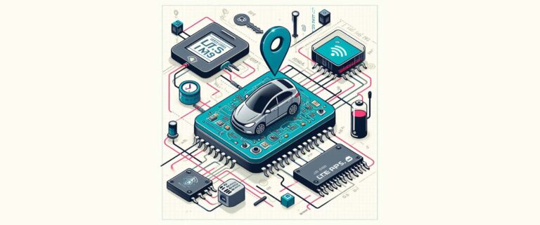
CarTrack asset tracker
Low-power asset tracker communicating GPS position over LTE-M wireless network, with user-friendly dashboards.
This project was initially published on MakerPro for the NXP FRDM Contest proposed by NXP and DigiKey during the summer 2024. Unfortunately, I was not a finalist this time. Congratulations to the winners!
Bill of Materials:
- NXP FRDM-MCXA153 (Developement kit)
- SIM7000G-TE-KIT (LTE-M + GPS module)
- LTE-M SIM Card, from 1nce
- Custom PCB
Special thanks
I discovered this project at Embedded World in April 2024, where I got the developement board for free by DigiKey and NXP. My first thanks are going to them as they provided me the starting point and the occasion to make my project visible.
It was also my first “sponsored” project, and I’m very proud that companies such as EBV Elektronik and 1nce supported me by giving for free the LTE-M + GPS module and some SIM cards to experiment with. Specific people will recognize themselves, thanks again for your trust !
Context
With this project, I made it impossible to lose my car on a parking. Thanks to a GPS and LTE-M module tied to the FRDM-MCXA153 through a custom-made shield, it acquires the position then transmitts it to an API with the least energy possible. The asset can never be lost, as it’s both battery and “mains” powered. More than that, the positions history is always kept even without network coverage thanks to a buffering technique.
Hardware concept
What would be a project without hardware, right? As you can see on the hardware concept below, the FRDM-MCXA153 board is the central point of the system. This is a very interesting platform with a state-of-the-art ARM Cortex-M33 MCU with its security and very low-power features.
Thanks to a custom shield board designed with Altium Designer, it’s connected to a SIM7000G GPS and LTE-M modem over a UART interface. For the SIM card and data subscription, I trusted 1nce which provides IoT services with a fixed amount of data for a duration of 10 years. In addition, an EEPROM and an accelerometer are available through the I2C bus. Of course, I can’t omit the temperature sensor of the board itself, connected over I3C. Finally, the battery voltage measurement is implemented with the ADC.
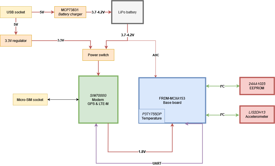
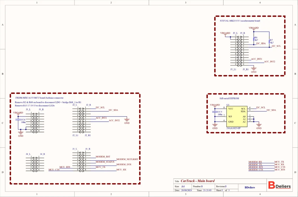
The actual schematics of the project can be seen below.
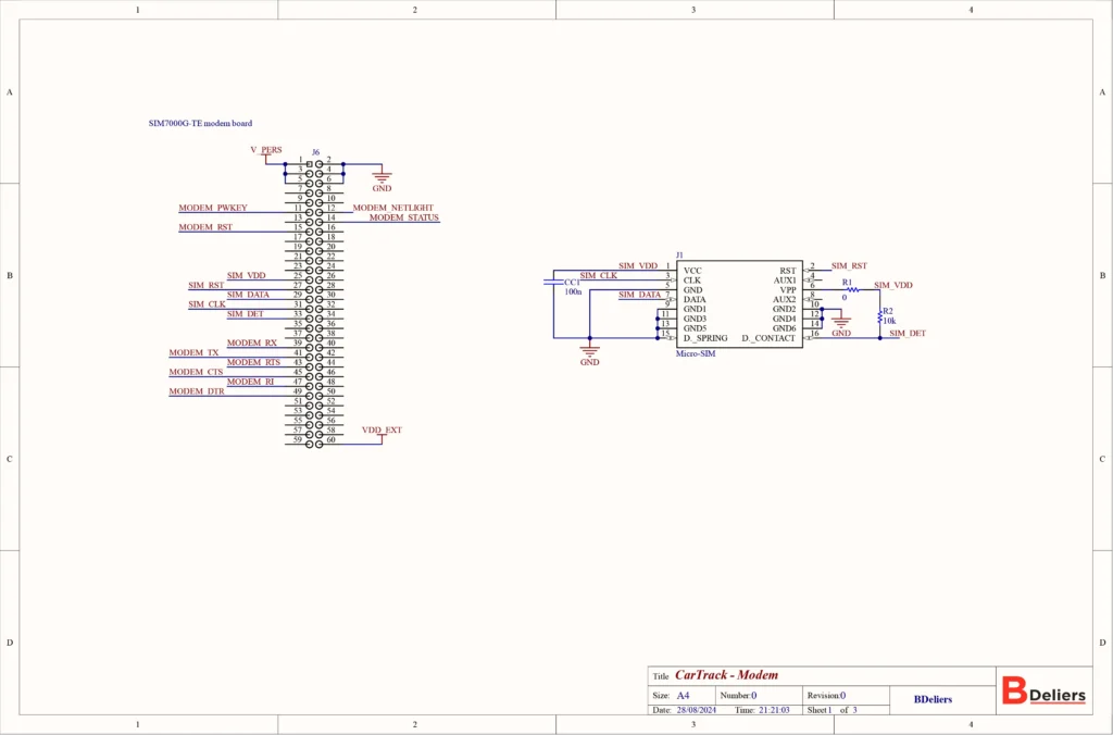
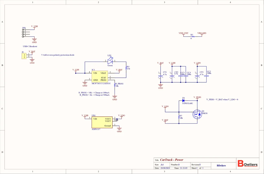
Power tree
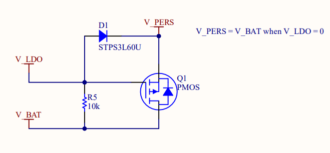
The whole system is powered by the 5V USB input of the shield when it’s plugged, and from a LiPo battery when the USB is not powered on. This is thanks to the piece of hardware that you can see on the schematic part below. When V_LDO is zero, the PMOS transistor starts to conduct and the V_BAT goes through it to be connected to V_PERS (which stands for Persistent). When the V_LDO is there, it goes through the diode and makes V_PERS equal to V_LDO – D1_dropout. This V_PERS is routed to the modem board directly.
The modem board works with 1.8V interfaces. As it has an integrated voltage regulator that is able to go from the battery’s voltage to 1.8V, the FRDM board get its power from it. Out of the box, the FRDM board takes its own 3.3V from a regulator connected to the USB port. To make it work with 1.8V, the board has LDO regulator disconnected. The onboard LEDs are disconnected too, in order to reduce energy consumption. A side-effect of this is that the MCXA153 MCU can’t be programmed anymore by the onboard MCU-Link, which needs the 3.3V from the LDO. Then, I programmed mine with a J-Link, connected to the J18 header.
All of this will enable our system to always get and share its position, by consuming as low energy as possible.
PCB design and milling
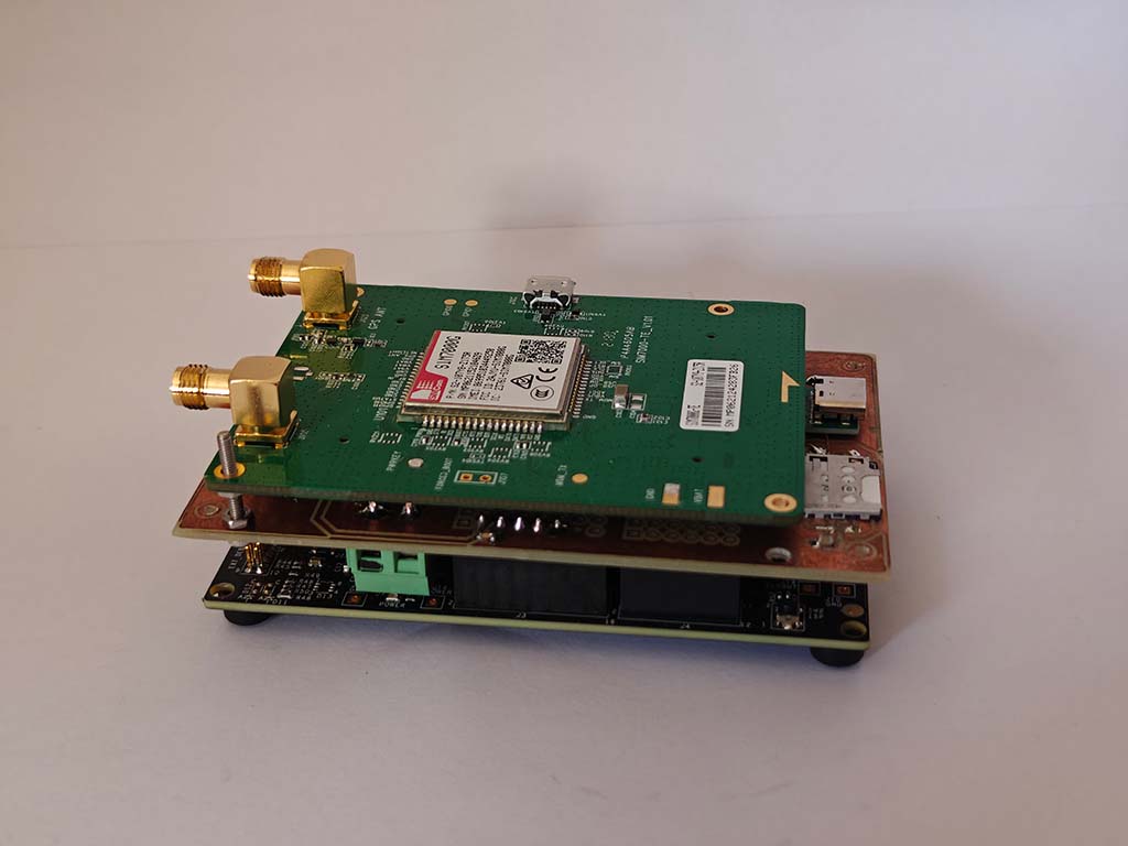
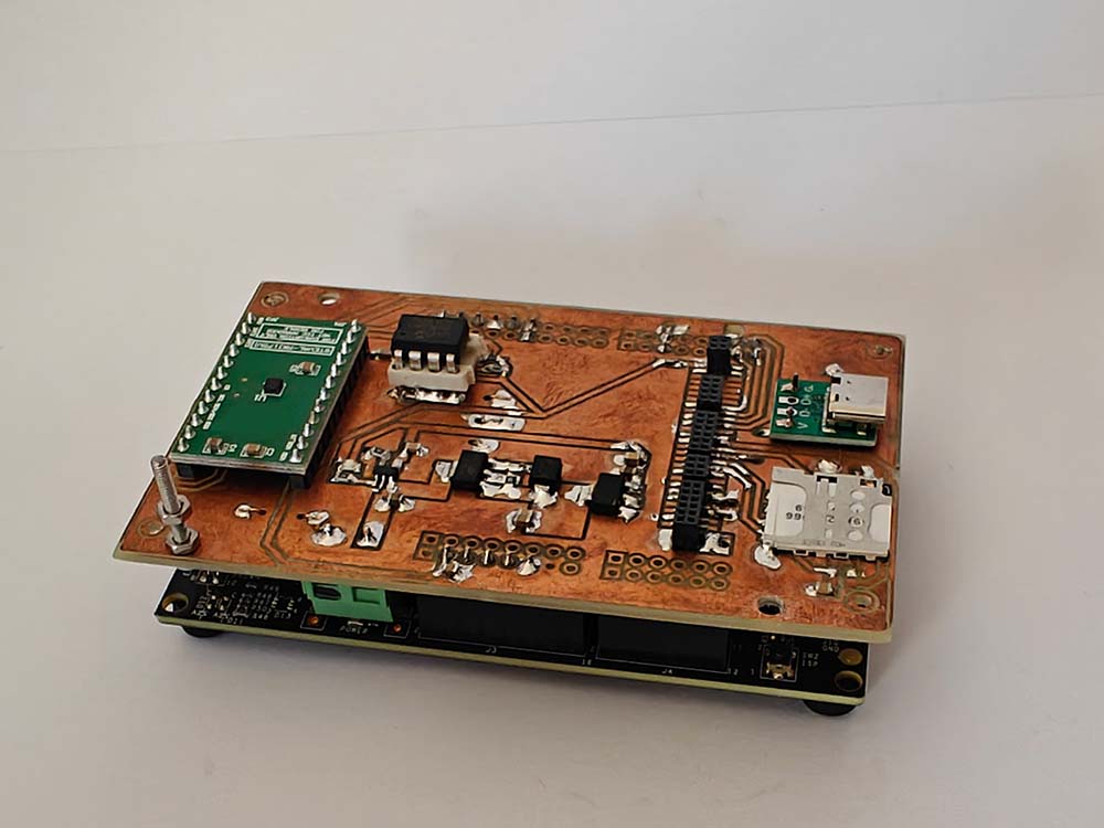
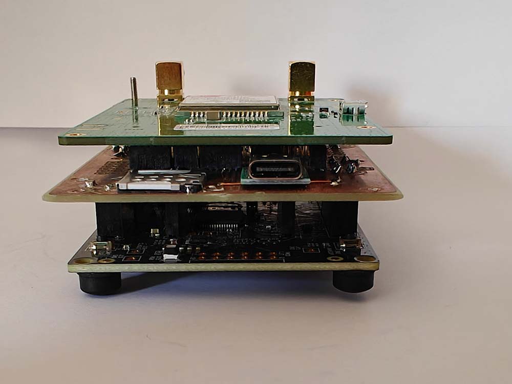
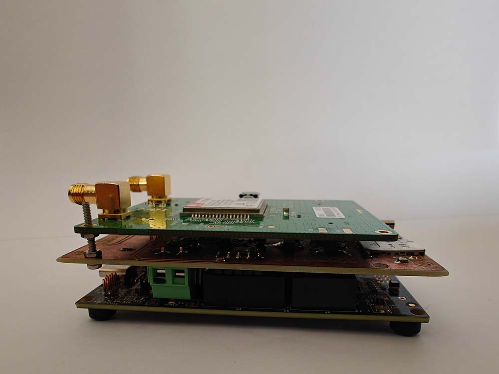
I designed the shield PCB to be stackable on top of the FRDM-MCXA153, plugged in the FRDM headers. I wanted it to be the same dimensions as the carrier board, and I was able to do so, even if it’s a single copper-sided PCB. The shield carries all the peripherals described previously. For the modem and the accelerometer, I used some demonstration kits. The SIM7000G_TE module is almost the size of the shield, so when everything is plugged-in, it looks like an electronics sandwich.
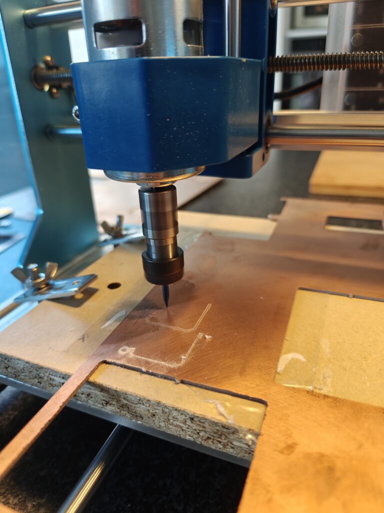
To make this PCB, I used my CNC milling machine and a single-side copper PCB. I’m very happy about the result because I had no short-circuit between the tracks.
Software concept
All of this beautiful hardware is nice, but what would it be without a smart software?
MCU Software
On the MCU side, the software is quite advanced. I used the NXP MCUXpresso IDE to develop my app.
Drivers level
First, I configured all my peripherals and I/O with the configurator. It’s a very handy tool. I use one UART peripheral for the logging and one to communicate with the modem. The I3C bus is configured and used for the FRDM’s onboard temperature sensor. Then, the I2C bus is there for the accelerometer and the EEPROM memory. The OS Timer is used to wake up the MCU from sleep, and the ADC to measure the battery.
On top of this low-level initialization, I wrote a big driver for the modem. The modem is controlled by AT commands (as most of the modems). It uses the UART, with the DMA. Indeed, as the modem can communicate asynchronously, it’s important to let the reception process be automatic. This driver is in charge of configuring the modem, enabling the GPS and connecting to the mobile network. Once it’s configured and connected, it’s ready to send the position.
I used the LTE-M wireless technology. It’s a low-power wide-area network radio communication designed for IoT. On the application protocol, I use the CoAP protocol (Constrained Application Protocol) which is based on UDP and optimized for low-data transmission, leading to power and data plan savings.
Busines-logic
A flowchart is better than a thousand words.
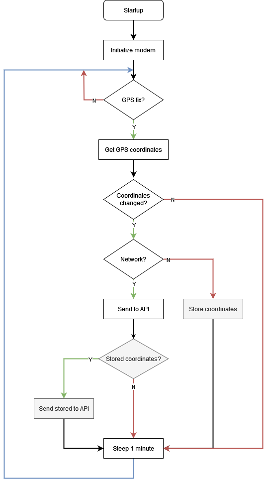
At startup, the board and all its peripherals are initialized. Then, when there is a GPS fix available, the coordinates are retrieved. If the current position is different from the previous one (with a few meters hysteresis), we continue. Otherwise, the MCU and the modem goes to sleep, to avoid sending useless data online. When data has to be sent but no network is available, it’s stored on the EEPROM to be sent later when the network will be available. When the network is ready, all the pending data is sent. This process is repeated each minute, when the system wakes up from sleep.
The data sent needs to be consistent over all the API process. Indeed, I don’t only send the GPS coordinates (latitude and longitude) but the altitude, speed over ground, temperature and battery level are also sent online. To have this consistency, I use Google’s Protobuffers. It’s a way of describing and structuring data which is generic to all programming languages. Your structure is filled in the software’s language (C in my case) then transformed to a generic Protobuffer. When it arrives on the other side of the API, it will be decoded to any other compatible language.
The grayed parts of the flowchart (the stored coordinates part) are not implemented yet, that’s part of the possible improvements. That’s just a matter of code, as the hardware is there. Same for the accelerometer which I would like to use to wake the MCU up when the asset starts to move. That’s interesting to wake up only on need and not on a fixed time base to spare even more energy.
The software is available on my GitHub. I developed it with C++ to leverage the power of Object-Oriented Programming. The lowest layers were generated by MCUXpresso and it worked flawlessly. It was really handy to rely on the fsl libraries, available for each peripheral of the MCU.
API and dashboards
The last part of the system has to be very handy to use. I speak about the dashboard of course.
First API
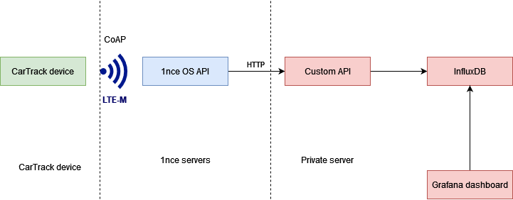
When the positioning data leaves the CarTrack module, it goes to the 1nce OS API over CoAP protocol on the LTE-M network. The interesting thing about the 1nce OS API is that it handles all the authentication based on the ICCID of the SIM card, which is a unique identified for the card. If the card is recognized to belong to 1nce, the data sent to their API is accepted. It avoided me to bother with edge cybersecurity and cryptography.
Second API
After the 1nce OS API, the payload is forwarded over HTTPS to a custom-made API that I host on my personal server. This API is written in JavaScript and leverages the power of NodeJS and Express to serve such a service. When the data arrives in my API, the authenticity of the sender is checked (is it the real 1nce OS?) then the payload data is checked and retrieved. As it contains the Protobuffer of my tracking information, it’s decoded and voilà! The data from a C program is now JSON, perfectly usable by JavaScript.
The data point is stored in to an InfluxDB bucket. InfluxDB is a database management system, made for time-series with aim for high-performances. That’s it for the APIs!
And dashboard!
Let’s summarize: the position (and surrounding data) was acquired, sent and transferred to a chain of APIs. It’s finally stored and available in a database. Let’s display it of course!
To make such dashboards, it’s useless to re-invent the wheel. Grafana does this perfectly. Through a web-interface, Grafana is able to make dashboards with any kind of data very easily. Even better, it can get this data from various sources, including InfluxDB.
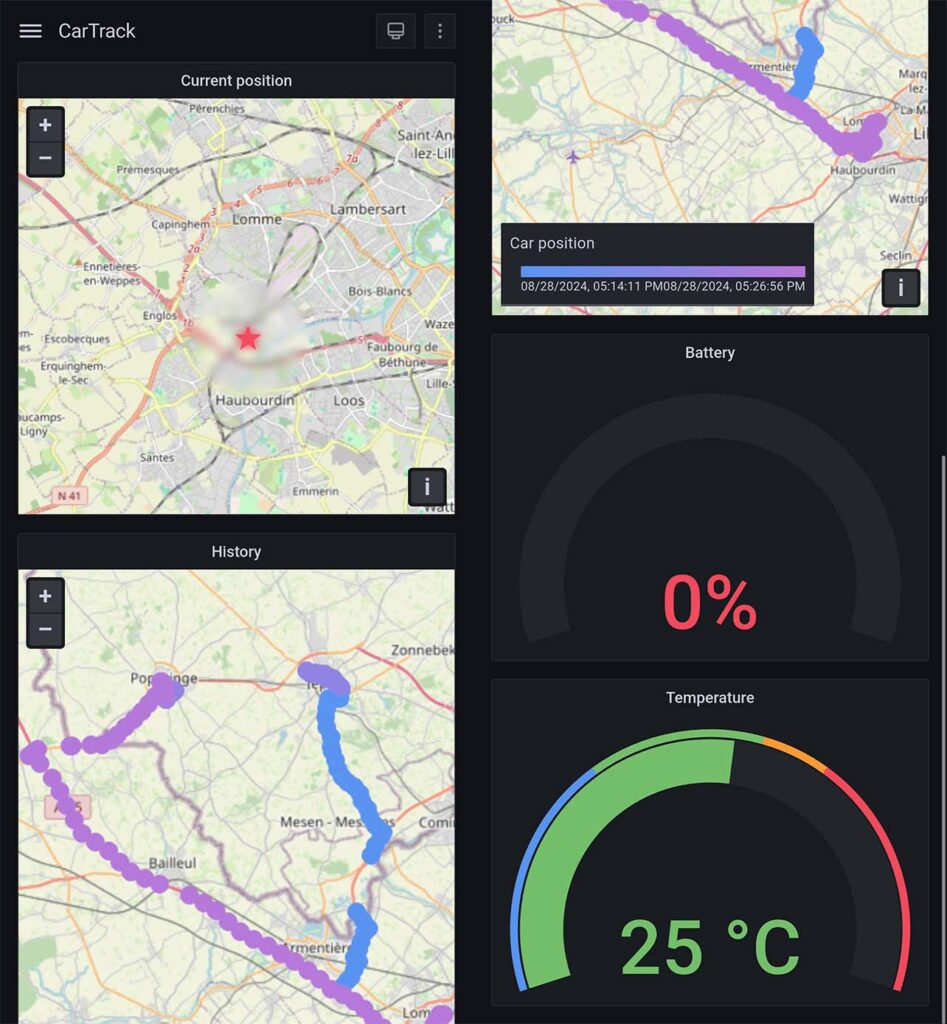
Using a “geomap” widget, I first display the last position of the asset, then the points of the last x hours. The most purple the point is, the more recent it is. Finally, I added battery and temperature gauges. As you can see on the pictures, it’s very convenient to see on a smartphone, but you can also view it from a desktop. Interesting feature, when clicking on a point, a Google Maps link is proposed to navigate to its coordinates. Smart!
Conclusion
To conclude, I had fun making this project. The MCXA153 is a very powerful and power-efficient MCU, provided with nice tools to configure it and make it work. Leveraging this MCU with the network capabilities of the SIM7000G modem for GPS and LTE-M permitted me to create a very stable and strong proof of concept. The complete API chain finished by the dashboard makes it very convenient to use.
Of course, implementing the data-buffering part would make it even better to keep a 100% quality of service and losing no data at all.
For sure, the next step of this project will be to make a real PCB to convert this proof of concept and all its development boards to a single board system with the best robustness and reliability.
![]()

